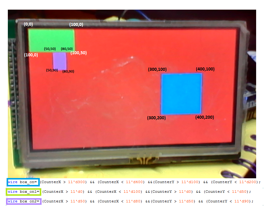
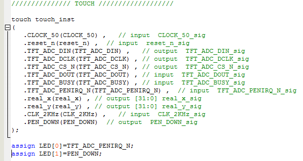
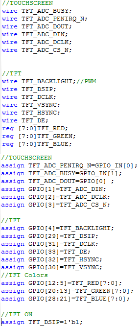
To use the TouchScreen of the Screen, we will be driving the chip XPT2046( On the Verilog code you will find that the Buses "real_x and real_y" are carring the coordingates where the touch screen is being pressed, and that the wire TFT_ADC_PENIRQ_N carries the interruption so you can determine when the screen was touched. You can use this implementation, and wire it up to any soft processor, FSM, or logic you desire. Enjoy! Once you have created the clock and as you have already the video sync verilog file, you can hook them up on the top file of your Quartus project. if you implemented the following example you will see on the TFT screen, a red background with a blue box drawn on the coordinates(x=10,y=55) with a width of 70 pixels, and height of 70 pixels. So let's say now you wanted to implement a GUI using only Verilog, and taking advantage that you have access to a touch screen as well. Imagine you need to create a GUI of three buttons, which we could simply describe as boxes, as it is shown in the following image. Once you have drawn these 3 boxes on the screen, you could now bind them to a touch screen action, using the stand alone touch screen module given in the section stand alone touch screen after instantiating the touch screen verilog module on your top module, you can use "real_x, and real_y" to know the position where the screen is being touched, and the PENIRQ to determine if the screen is pressed. The above instantiation, has a new output named "PEN_DOWN", which is simply a delayed or anti bouncer representation of TFT_ADC_PENIRQ_N, which is useful to avoid bouncing. You can download this modified touched driver here To correlate the position of the touchscreen and the drawn boxes, you can simple add the condition using the buses "real_x, and real_y" in the following way So the wire "box_oprimido" carries the condition if the touchscreen is being pressed, the real_x is greater than the position 300 and less than 400, and the real_y is greater than the position 100 and less than 200, this wire will be set to 1. So for our logic this means that the "box_on" has been pressed by the user. You can also use this wire to act the input of a color multiplexer, so if you want to change the color of the box when you press the button, you can. Here the modified code to make this example work. Note: You need to add to the PLL a clock of 2KHz to make sure the touch screen driver works accordingly for the antibouncer(PEN_DOWN) Then the results will be what is shown in the video below You can download the template or example if you want from here:
![]() DE0_NANO_TFT_PSP.zip) y descomprimala en una ruta sin espacios y corta.
DE0_NANO_TFT_PSP.zip) y descomprimala en una ruta sin espacios y corta.
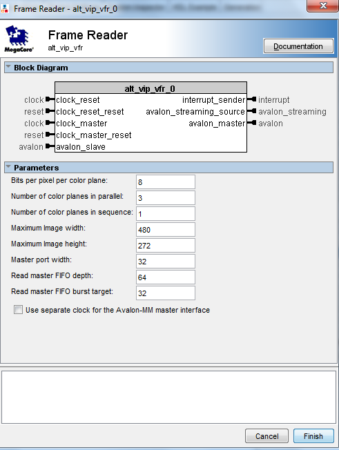
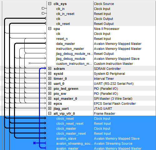
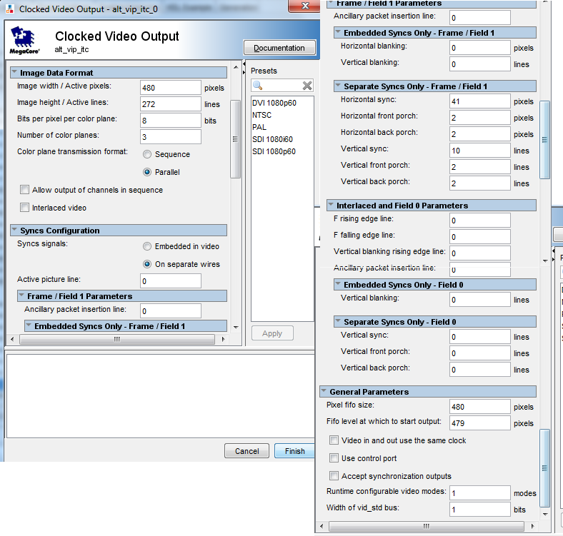
![]() datasheet.
datasheet.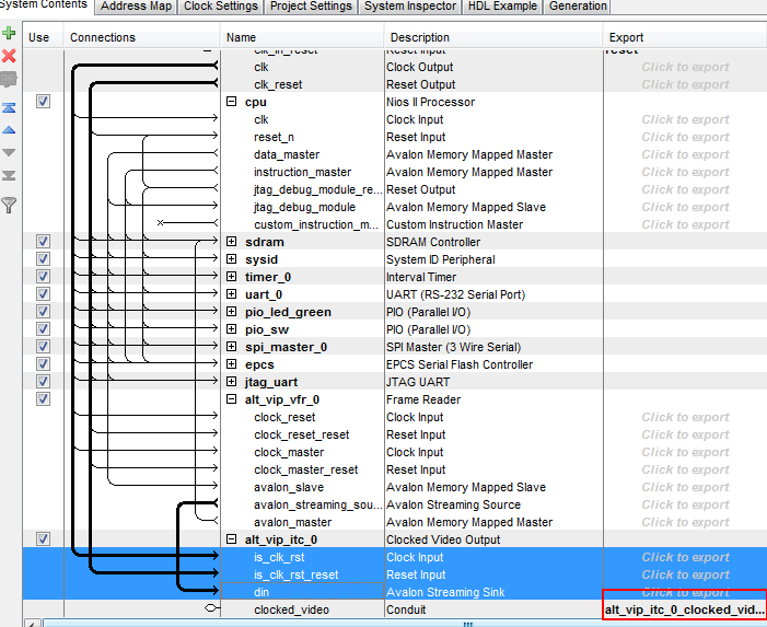
480x272x4=522240 Bytes=0x7f800 Bytes ==> si se quiere 1 Frame.
480x272x4x2=1044480 Bytes=0xff000 Bytes==> si se quiere 2 Frame.
En nuestro diseño dejaremos 2 Frames entonces necesitamos dejar un espacio destinado a Video del tamaño de 480x272x4x2=1044480 Bytes=0xff000 Bytes
deben ser agregados al Exception Vector.
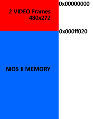
Esto se hace para que el procesador se limite a trabajar desde este punto de partida, y no existan problemas de tener Video donde no debemos tenerlo.

![]() HX8257.pdf):
HX8257.pdf):

![]() video_test.zip) y copie en el proyecto "video_test" los archivos que hay en el.
video_test.zip) y copie en el proyecto "video_test" los archivos que hay en el.

![]() KT43B0E8257-40A (1).pdf), and it can be driven using the following Verilog Hardware Description, you can connect the pins of the screen wherever you want on the FPGA GPIO, and use it.
KT43B0E8257-40A (1).pdf), and it can be driven using the following Verilog Hardware Description, you can connect the pins of the screen wherever you want on the FPGA GPIO, and use it.![]() Touch Driver Verilog Code Download
Touch Driver Verilog Code Download//TOUCHSCREEN
assign TFT_ADC_PENIRQ_N=GPIO_IN[0];
assign TFT_ADC_BUSY=GPIO_IN[1];
assign GPIO[0] =1'bz;
assign TFT_ADC_DOUT=GPIO[0] ;
assign GPIO[1]=TFT_ADC_DIN;
assign GPIO[2]=TFT_ADC_DCLK;
assign GPIO[3]=TFT_ADC_CS_N;
wire [11:0] x_coord;
wire [11:0] y_coord;
reg [11:0] x_coord_reg;
reg [11:0] y_coord_reg;
wire new_coord;
//Touch
localparam X_ADC_UPPER_RIGTH=3975;
localparam X_POS_UPPER_RIGTH=479;
localparam X_ADC_LOWER_LEFT=112;
localparam X_POS_LOWER_LEFT=0;
localparam Y_ADC_UPPER_RIGTH=4032;
localparam Y_POS_UPPER_RIGTH=0;
localparam Y_ADC_LOWER_LEFT=110;
localparam Y_POS_LOWER_LEFT=271;
wire [11:0] x_coord;
wire [11:0] y_coord;
wire new_coord;
adc_spi_controller u2 (
.iCLK(CLOCK_50),
.iRST_n(reset_n),
.oADC_DIN(TFT_ADC_DIN),
.oADC_DCLK(TFT_ADC_DCLK),
.oADC_CS(TFT_ADC_CS_N),
.iADC_DOUT(TFT_ADC_DOUT),
.iADC_BUSY(TFT_ADC_BUSY),
.iADC_PENIRQ_n(TFT_ADC_PENIRQ_N),
.oX_COORD(x_coord),
.oY_COORD(y_coord),
.oNEW_COORD(new_coord),
);
wire [31:0] numeratorX=(y_coord-X_ADC_LOWER_LEFT)*(X_POS_UPPER_RIGTH-X_POS_LOWER_LEFT);
wire [31:0] denominatorX=X_ADC_UPPER_RIGTH-X_ADC_LOWER_LEFT;
reg [31:0] real_x;
wire [31:0] numeratorY=(x_coord-Y_ADC_LOWER_LEFT)*(Y_POS_LOWER_LEFT-Y_POS_UPPER_RIGTH);
wire [31:0] denominatorY=Y_ADC_UPPER_RIGTH-Y_ADC_LOWER_LEFT;
reg[31:0] real_y;
always@(posedge CLOCK_50)
begin
real_y<=real_y;
real_x<=real_x;
if(!TFT_ADC_PENIRQ_N && new_coord)
begin
real_y<= Y_POS_LOWER_LEFT-(numeratorY/denominatorY);
real_x<= (numeratorX/denominatorX)+X_POS_LOWER_LEFT;
end
end
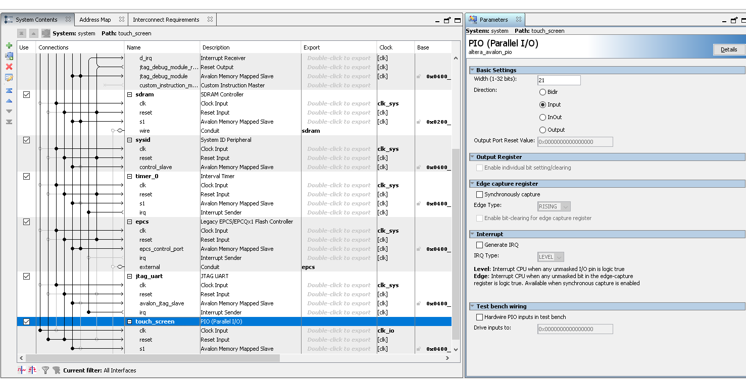
wire [20:0]touch_to_nios={~TFT_ADC_PENIRQ_N,real_x[9:0],real_y[9:0]};//
system u0 (
.clk_clk (sys_clk), // clk.clk
.reset_reset_n (reset_n), // reset.reset_n
.clk_io_clk (io_clk), // clk_io.clk
.reset_io_reset_n (reset_n),
//EPCS
.epcs_sdo (EPCS_ASDO), // epcs.sdo
.epcs_data0 (EPCS_DATA0), // .data0
.epcs_dclk (EPCS_DCLK), // .dclk
.epcs_sce (EPCS_NCSO), // .sce
//SDRAM
.sdram_dqm (DRAM_DQM), // sdram.dqm
.sdram_ras_n (DRAM_RAS_N), // .ras_n
.sdram_cs_n (DRAM_CS_N), // .cs_n
.sdram_we_n (DRAM_WE_N), // .we_n
.sdram_dq (DRAM_DQ), // .dq
.sdram_cke (DRAM_CKE), // .cke
.sdram_addr (DRAM_ADDR), // .addr
.sdram_ba (DRAM_BA), // .ba
.sdram_cas_n (DRAM_CAS_N), // .cas_n
//Touch Screen
.touch_screen_export (touch_to_nios[20:0]));
![]() TOUCH_EVENT.h
TOUCH_EVENT.h ![]() TOUCH_EVENT.c) to use it on your Nios II designs or use it as guidance to port it over other soft core, and test it with the following main code.
TOUCH_EVENT.c) to use it on your Nios II designs or use it as guidance to port it over other soft core, and test it with the following main code./*
* TOUCH_EVENT.c
*
* Created on: 1/04/2014
* Author: Holguer A. Becerra
* This email address is being protected from spambots. You need JavaScript enabled to view it.
*/
#include <stdio.h>
#include <unistd.h> // usleep (unix standard?)
#include "io.h" // I/O access
#include "system.h" // HAL system
#include "./touch_driver/TOUCH_EVENT.h"
int main(){
// init Touch
int result;
int event=0;
int pos_x,pos_y;
while(1){
event=event_is_up(&pos_x, &pos_y);
if(event==0){
printf("Evento down x=%d y=%d\n",pos_x,pos_y);
}
else if(event==1){
printf("Evento UP x=%d y=%d\n",pos_x,pos_y);
}
usleep(100000);
}
return 0;
}
![]() TouchScreen Nios II.zip)
TouchScreen Nios II.zip)
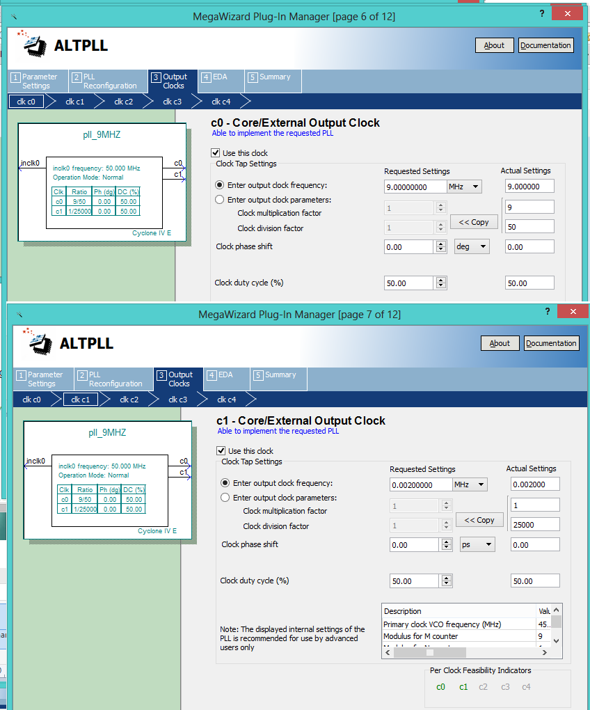
![]() PSPVideoSync) for this particular TFT.
PSPVideoSync) for this particular TFT.
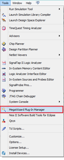
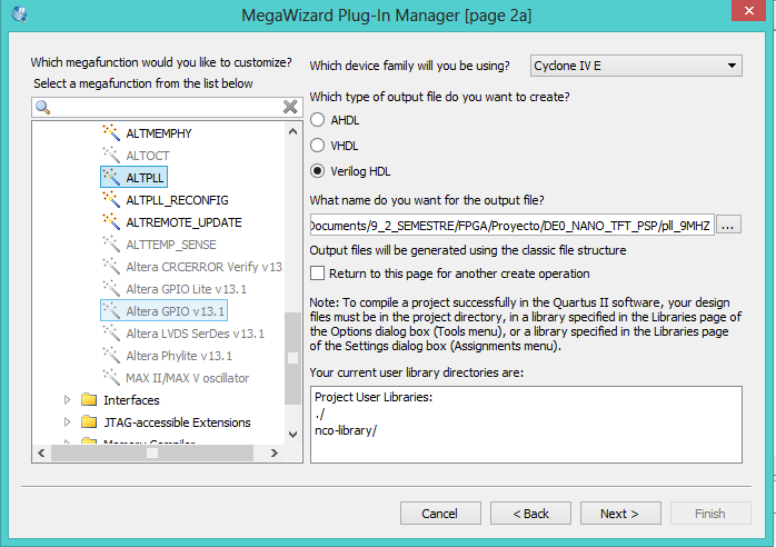
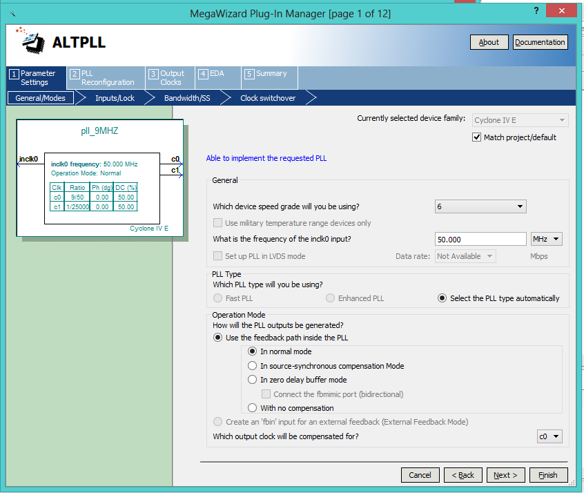
//TFT
wire TFT_BACKLIGHT;//PWM
wire TFT_DSIP;
wire TFT_DCLK;
wire TFT_VSYNC;
wire TFT_HSYNC;
wire TFT_DE;
reg [7:0]TFT_RED;
reg [7:0]TFT_GREEN;
reg [7:0]TFT_BLUE;

///VGA
wire [10:0]CounterX;
wire [10:0]CounterY;


//TFT
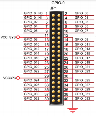
assign GPIO[4]=TFT_BACKLIGHT;
assign GPIO[29]=TFT_DSIP;
assign GPIO[31]=TFT_DCLK;
assign GPIO[33]=TFT_DE;

assign GPIO[32]=TFT_HSYNC;
assign GPIO[30]=TFT_VSYNC;

//TFT Colors
assign GPIO[12:5]=TFT_RED[7:0];
assign GPIO[20:13]=TFT_GREEN[7:0];
assign GPIO[28:21]=TFT_BLUE[7:0];


//TFT ON
assign TFT_DSIP=1'b1;
assign TFT_BACKLIGHT=1'b1;

//////////////////PLL VGA /////////////

pll_9MHZ	pll_9MHZ_inst (
	.inclk0 ( CLOCK_50 ),
	.c0 ( TFT_DCLK )// RELOJ 9MHZ
	);


////////////////// SINCRONIZADOR VGA ////////////

mi_vga mi_vga_inst
(
	.clk(TFT_DCLK) ,	// input  clk_sig
	.h_sync(TFT_HSYNC) ,	// output  h_sync_sig
	.v_sync(TFT_VSYNC) ,	// output  v_sync_sig
	.video_on(TFT_DE) ,	// output  video_on_sig
	.pixel_x(CounterX) ,	// output [N-1:0] pixel_x_sig
	.pixel_y(CounterY) 	// output [N-1:0] pixel_y_sig
);


wire square_on= (CounterX > 11'd10) && (CounterX < 11'd80) &&(CounterY > 11'd55) && (CounterY < 11'd125);

/////MUX DE VIDEO ////
always@(negedge TFT_DCLK)
begin
   if(!TFT_DE)
	begin
	     TFT_RED<=8'h00;
		  TFT_GREEN <=8'd0;
		  TFT_BLUE <=8'd0;
	end
	else
	begin
	     TFT_RED<=8'hFF;
		 TFT_GREEN<=8'h00;
		 TFT_BLUE <=8'h00;
		 if(square_on)
		 begin
			TFT_RED<=8'h00;
		 	TFT_GREEN<=8'h00;
			TFT_BLUE <=8'hFF;
		 end
   	end
end
GUI on TFT using Only Verilog
![]() touch.v
touch.v![]()
wire box_on= (CounterX > 11'd300) && (CounterX < 11'd400) &&(CounterY > 11'd100) && (CounterY < 11'd200);
wire box_on1= (CounterX > 11'd0) && (CounterX < 11'd100) &&(CounterY > 11'd0) && (CounterY < 11'd80);
wire box_on2= (CounterX > 11'd150) && (CounterX < 11'd250) &&(CounterY > 11'd50) && (CounterY < 11'd100);

wire box_oprimido=((PEN_DOWN==1'b0) & (real_x[31:0]>11'd300) & (real_x[31:0]<11'd400) &   (real_y[31:0]>11'd100) & (real_y[31:0]<11'd200));
wire [23:0]color_box=box_oprimido?24'h00ff00:24'h0000ff;

wire box_oprimido_1=((PEN_DOWN==1'b0) & (real_x[31:0]>11'd0) & (real_x[31:0]<11'd100) &   (real_y[31:0]>11'd0)   & (real_y[31:0]<11'd80));
wire [23:0]color_box_1=box_oprimido_1?24'h0000ff:24'h00ff00;

wire box_oprimido_2=((PEN_DOWN==1'b0) & (real_x[31:0]>11'd150) & (real_x[31:0]<11'd250) & (real_y[31:0]>11'd50)  & (real_y[31:0]<11'd100));
wire [23:0]color_box_2=box_oprimido_2?24'h000000:24'hf00ff0;
//TOUCHSCREEN
wire TFT_ADC_BUSY;
wire TFT_ADC_PENIRQ_N;
wire TFT_ADC_DOUT;
wire TFT_ADC_DIN;
wire TFT_ADC_DCLK;
wire TFT_ADC_CS_N;


wire [31:0]  real_x;
wire [31:0]  real_y;

wire PEN_DOWN;


//TFT
wire TFT_BACKLIGHT;//PWM
wire TFT_DSIP;
wire TFT_DCLK;
wire TFT_VSYNC;
wire TFT_HSYNC;
wire TFT_DE;
reg [7:0]TFT_RED;
reg [7:0]TFT_GREEN;
reg [7:0]TFT_BLUE;

///VGA
wire [10:0]CounterX;
wire [10:0]CounterY;


//TOUCHSCREEN
assign TFT_ADC_PENIRQ_N=GPIO_IN[0];
assign TFT_ADC_BUSY=GPIO_IN[1];
assign TFT_ADC_DOUT=GPIO[0] ;
assign GPIO[1]=TFT_ADC_DIN;
assign GPIO[2]=TFT_ADC_DCLK;
assign GPIO[3]=TFT_ADC_CS_N;

//TFT
assign GPIO[4]=TFT_BACKLIGHT;
assign GPIO[29]=TFT_DSIP;
assign GPIO[31]=TFT_DCLK;
assign GPIO[33]=TFT_DE;

assign GPIO[32]=TFT_HSYNC;
assign GPIO[30]=TFT_VSYNC;

//TFT Colors
assign GPIO[12:5]=TFT_RED[7:0];
assign GPIO[20:13]=TFT_GREEN[7:0];
assign GPIO[28:21]=TFT_BLUE[7:0];


//TFT ON
assign TFT_DSIP=1'b1;
assign TFT_BACKLIGHT=1'b1;

wire reset_n=1'b1;

//////////////////PLL VGA /////////////

pll_9MHZ	pll_9MHZ_inst (
	.inclk0 ( CLOCK_50 ),
	.c0 ( TFT_DCLK ),// RELOJ 9MHZ
	.c1(CLK_2KHz) //anti bouncer clock
	);


////////////////// SINCRONIZADOR VGA ////////////

mi_vga mi_vga_inst
(
	.clk(TFT_DCLK) ,	// input  clk_sig
	.h_sync(TFT_HSYNC) ,	// output  h_sync_sig
	.v_sync(TFT_VSYNC) ,	// output  v_sync_sig
	.video_on(TFT_DE) ,	// output  video_on_sig
	.pixel_x(CounterX) ,	// output [N-1:0] pixel_x_sig
	.pixel_y(CounterY) 	// output [N-1:0] pixel_y_sig
);

///////////////// TOUCH ///////////////////

touch touch_inst
(
	.CLOCK_50(CLOCK_50) ,	// input  CLOCK_50_sig
	.reset_n(reset_n) ,	// input  reset_n_sig
	.TFT_ADC_DIN(TFT_ADC_DIN) ,	// output  TFT_ADC_DIN_sig
	.TFT_ADC_DCLK(TFT_ADC_DCLK) ,	// output  TFT_ADC_DCLK_sig
	.TFT_ADC_CS_N(TFT_ADC_CS_N) ,	// output  TFT_ADC_CS_N_sig
	.TFT_ADC_DOUT(TFT_ADC_DOUT) ,	// input  TFT_ADC_DOUT_sig
	.TFT_ADC_BUSY(TFT_ADC_BUSY) ,	// input  TFT_ADC_BUSY_sig
	.TFT_ADC_PENIRQ_N(TFT_ADC_PENIRQ_N) ,	// input  TFT_ADC_PENIRQ_N_sig
	.real_x(real_x) ,	// output [31:0] real_x_sig
	.real_y(real_y) ,	// output [31:0] real_y_sig
	.CLK_2KHz(CLK_2KHz) ,	// input  CLK_2KHz_sig
	.PEN_DOWN(PEN_DOWN) 	// output  PEN_DOWN_sig
);

assign LED[0]=TFT_ADC_PENIRQ_N;
assign LED[1]=PEN_DOWN;


/// GUI logic
wire box_on= (CounterX > 11'd300) && (CounterX < 11'd400) &&(CounterY > 11'd100) && (CounterY < 11'd200);
wire box_on1= (CounterX > 11'd0) && (CounterX < 11'd100) &&(CounterY > 11'd0) && (CounterY < 11'd80);
wire box_on2= (CounterX > 11'd150) && (CounterX < 11'd250) &&(CounterY > 11'd50) && (CounterY < 11'd100);

wire box_oprimido=((PEN_DOWN==1'b0) & (real_x[31:0]>11'd300) & (real_x[31:0]<11'd400) &   (real_y[31:0]>11'd100) & (real_y[31:0]<11'd200));
wire [23:0]color_box=box_oprimido?24'h00ff00:24'h0000ff;

wire box_oprimido_1=((PEN_DOWN==1'b0) & (real_x[31:0]>11'd0) & (real_x[31:0]<11'd100) &   (real_y[31:0]>11'd0)   & (real_y[31:0]<11'd80));
wire [23:0]color_box_1=box_oprimido_1?24'h0000ff:24'h00ff00;

wire box_oprimido_2=((PEN_DOWN==1'b0) & (real_x[31:0]>11'd150) & (real_x[31:0]<11'd250) & (real_y[31:0]>11'd50)  & (real_y[31:0]<11'd100));
wire [23:0]color_box_2=box_oprimido_2?24'h000000:24'hf00ff0;

/////MUX DE VIDEO ////
always@(negedge TFT_DCLK)
begin
   if(!TFT_DE)
	begin
	     TFT_RED[7:0]<=8'h00;
		 TFT_GREEN[7:0] <=8'd0;
		 TFT_BLUE[7:0] <=8'd0;
	end
	else
	begin
	     {TFT_RED[7:0],TFT_GREEN[7:0],TFT_BLUE[7:0]}<={8'hFF,8'h00,8'h00};
		 if(box_on)
		 begin
			{TFT_RED[7:0],TFT_GREEN[7:0],TFT_BLUE[7:0]}<=color_box[23:0];
		 end
		 else if(box_on1)
		 begin
			{TFT_RED[7:0],TFT_GREEN[7:0],TFT_BLUE[7:0]}<=color_box_1[23:0];
		 end
		 else if(box_on2)
		 begin
			{TFT_RED[7:0],TFT_GREEN[7:0],TFT_BLUE[7:0]}<=color_box_2[23:0];
		 end
   	end
end
![]() DE0_NANO_TFT_GUI_VERILOG.qar
DE0_NANO_TFT_GUI_VERILOG.qar
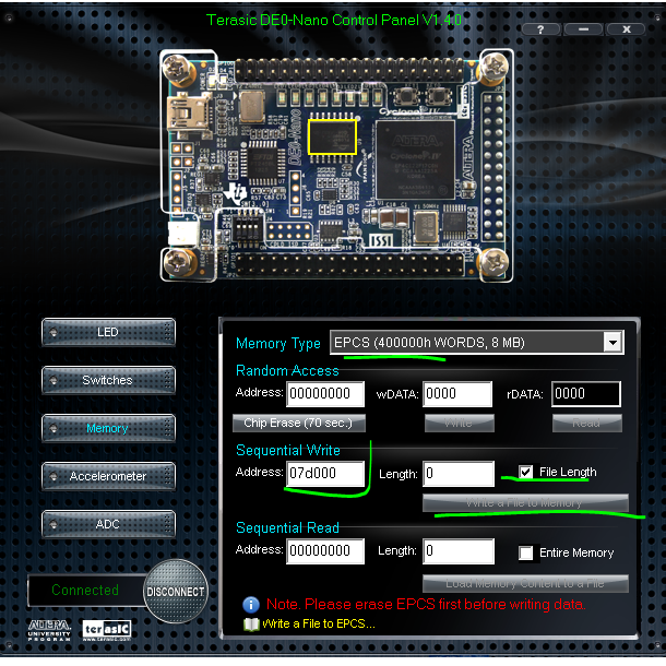
![]() DE0_Nano_ControlPanel_V1.4.0.zip), programe la EPCS desde la posición 0x7d000 con el archivo siguiente(.pce): JackieChan.pce
DE0_Nano_ControlPanel_V1.4.0.zip), programe la EPCS desde la posición 0x7d000 con el archivo siguiente(.pce): JackieChan.pce
PIN NO.
SYMBOL
DESCRIPTION
TYPE
FUNCTION
1
IRQ
Touch screen interrupt
output
Low level while the touch screen detects pressing
2
5V
5V power supply
input
5V power supply
3
MOSI
Touch screen SPI data input
input
Connects to SPI MOSI
4
MISO
Touch screen SPI data output
output
Connects to SPI MISO
5
SCK
Touch screen SPI clock
input
Connects to SPI SCK
6
SSEL
Touch screen chip select
input
Low active
7
PWM
Backlight brightness adjustment
input
Control the backlight brightness via PWM
8
GND
Ground
input
GND
9
BUSY
Touch screen busy
output
10
NC
11
R0
Data pin
input
Red data
12
R1
13
R2
14
R3
15
R4
16
R5
17
R6
18
R7
19
G0
Data pin
input
Green data
20
G1
21
G2
22
G3
23
G4
24
G5
25
G6
26
G7
27
B0
Data pin
input
Blue data
28
B1
29
B2
30
B3
31
B4
32
B5
33
B6
34
B7
35
DCLK
LCD clock
input
LCD clock signal
36
DSIP
NC
37
HSYNC
Horizontal Synchronization
input
Horizontal synchronous signal input
38
VSYNC
Vertical Synchronization
input
Vertical synchronous signal input
39
DE
Control mode selection
input
DE = 0 : SYNC mode
DE = 1 : DE mode
40
GND
Ground
input
GND
